

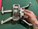
A DIY Air2 Arm Replacement, few Notes to be aware.
Had a bump with side of house that resulted in Air2S flying erratic at times and lack of control. Closer examination revealed Ft LEFT Arm Motor was slightly bent.
I have the DroneHacks Firmware Certificate, was concerned with DJI Service/Repair updating FW, removing DH Cert and preventing applying after repair.
Thus became a DIY job to retain DH Certificate and to maybe save a bit on DJI Repair.
The Left Arm had a slightly bent motor, no other damage was visible, but I had a full Neon Orange skin and the skin was pretty chewed & removed on the Right motor & Right side. So to play it safe, I ordered Lf & Rt Ft Arms/Motors.... that later was a Good Guess!
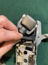
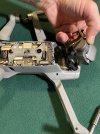
The Rt Arm's Shaft Mount Spring Hinge showed compression / deformation damage. Could not reinsert Arm Shaft on rebuild and spring catch wasn't good.
Note Photo: Arm Shaft Bent from impact, should be smooth sides no creases in shaft.
NOTE: Didn't order these originally, so 1 arm is pending shaft mount to complete project.
Plenty of videos on take down of the Mavic Air 2... not as many on Air 2S, but other than the Nose clip it's pretty identical in take-down.
View the YouTubes for overall Air 2 take-down, the following are a few notes I learned / discovered not mentioned in YouTubes.
1) New Arm Leads... don't need to be trimmed, they come cut to various lengths and a bit longer than OEM which is nice for DIY project.
2) Take several Photos, to help with screws, and specifically antenna & wire routing.
3) Take caution removing Nose cap, there are very small guide tabs on TOP & Sides... (many YouTubes appear to break a few & ignored).
4) Solder Iron: SmMed Electronics Tip (1/8" size) and about 800F worked for me on desolder & solder.
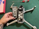
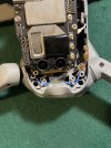
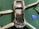
5) NO SCREW - One screw hole by OEM did not include a screw. Don't panic looking for missing screw! (Shown in Photo)
6) Remove MicroSD card prior to take-down.
7) Note in Videos, the 2 Rear screws for upper Housing. Very Deep in far Rear under Belly Plate.
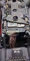
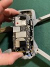
8) Removing Lower Circuit board, NOTE Tabs & Body mounts near USB-C & MicroSD ports.
* When removing board, take time to slightly spread the fuselage sides open to release & clear the small mount points.
* When reassembling, insure tabs are above Circuit board and board flush to screw mount posts.
9) Air2S Gimbal Ribbon cables. The Main Ribbon Micro-Connector, looks different from Air2 Videos. Does not pop-up easily... extreme caution to release connector, I found inner side released easier. When Reconnecting: Insure lining up the micro-connector prior to pushing down... These damage easy and not repairable, needs replacement board if damaged to insure contact connectivity is optimal.
10) Antenna Leads, Note OEM Antenna lead routing. Leads are cut to reach antenna socket without excess, and routing OEM makes a difference in length.
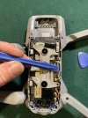
11) Resolder Arm Wires onto existing solder & Pads, add a small amount to complete. Take note of OEM wire routing & mount clip board. I found clipping new wires into mount board at proper length reaching solder pad eased performing a quick solder point. NOTE: Left & Right Wire Order is same, reference 1 while soldering other.
12) Remounting Lower Circuit Board: Take note of ribbon cable connectors, do not have them under board. Note Rear small Plastic POSTs to help align board, Note Side Tabs and gently pull out while working Board into craft from Rear to Forward. NOTE: Rear Contact Pad on Ribbon cable. Insure above Board and Antenna leads do not prevent it laying flush on copper pad.
13) Inserting Arm Shafts, NOTE the small Notch to align.
The fussy part for me, was the Ft Arm Shaft Mounts - Spring Pins.
These are a challenge, the spring is very stiff and aligning everything required patience.
My method, Insert Shaft and align with Arm's socket, once down close to mount posts, use the fuselage to move inner spring post about half way between snap stops.
Once centered in mid-way, you can gently align arm and push shaft and center pin through Arm's upper pin hole. Then Install the Rear screw to retain.
If you change the arms, take your time, go easy on solder... very small gage wires. Especially take your time on the Arm Shaft Springs!
For FREE - At bottom of photos: photo of Ft Antenna Legs, LED Covers & Screws.
If anyone wants, cost is shipping only.


Undamaged Ft Antenna Legs from old Arms.
Free to who would like... cost is shipping only.

Had a bump with side of house that resulted in Air2S flying erratic at times and lack of control. Closer examination revealed Ft LEFT Arm Motor was slightly bent.
I have the DroneHacks Firmware Certificate, was concerned with DJI Service/Repair updating FW, removing DH Cert and preventing applying after repair.
Thus became a DIY job to retain DH Certificate and to maybe save a bit on DJI Repair.
The Left Arm had a slightly bent motor, no other damage was visible, but I had a full Neon Orange skin and the skin was pretty chewed & removed on the Right motor & Right side. So to play it safe, I ordered Lf & Rt Ft Arms/Motors.... that later was a Good Guess!
The Rt Arm's Shaft Mount Spring Hinge showed compression / deformation damage. Could not reinsert Arm Shaft on rebuild and spring catch wasn't good.
Note Photo: Arm Shaft Bent from impact, should be smooth sides no creases in shaft.
NOTE: Didn't order these originally, so 1 arm is pending shaft mount to complete project.
Plenty of videos on take down of the Mavic Air 2... not as many on Air 2S, but other than the Nose clip it's pretty identical in take-down.
View the YouTubes for overall Air 2 take-down, the following are a few notes I learned / discovered not mentioned in YouTubes.
1) New Arm Leads... don't need to be trimmed, they come cut to various lengths and a bit longer than OEM which is nice for DIY project.
2) Take several Photos, to help with screws, and specifically antenna & wire routing.
3) Take caution removing Nose cap, there are very small guide tabs on TOP & Sides... (many YouTubes appear to break a few & ignored).
4) Solder Iron: SmMed Electronics Tip (1/8" size) and about 800F worked for me on desolder & solder.
5) NO SCREW - One screw hole by OEM did not include a screw. Don't panic looking for missing screw! (Shown in Photo)
6) Remove MicroSD card prior to take-down.
7) Note in Videos, the 2 Rear screws for upper Housing. Very Deep in far Rear under Belly Plate.
8) Removing Lower Circuit board, NOTE Tabs & Body mounts near USB-C & MicroSD ports.
* When removing board, take time to slightly spread the fuselage sides open to release & clear the small mount points.
* When reassembling, insure tabs are above Circuit board and board flush to screw mount posts.
9) Air2S Gimbal Ribbon cables. The Main Ribbon Micro-Connector, looks different from Air2 Videos. Does not pop-up easily... extreme caution to release connector, I found inner side released easier. When Reconnecting: Insure lining up the micro-connector prior to pushing down... These damage easy and not repairable, needs replacement board if damaged to insure contact connectivity is optimal.
10) Antenna Leads, Note OEM Antenna lead routing. Leads are cut to reach antenna socket without excess, and routing OEM makes a difference in length.
11) Resolder Arm Wires onto existing solder & Pads, add a small amount to complete. Take note of OEM wire routing & mount clip board. I found clipping new wires into mount board at proper length reaching solder pad eased performing a quick solder point. NOTE: Left & Right Wire Order is same, reference 1 while soldering other.
12) Remounting Lower Circuit Board: Take note of ribbon cable connectors, do not have them under board. Note Rear small Plastic POSTs to help align board, Note Side Tabs and gently pull out while working Board into craft from Rear to Forward. NOTE: Rear Contact Pad on Ribbon cable. Insure above Board and Antenna leads do not prevent it laying flush on copper pad.
13) Inserting Arm Shafts, NOTE the small Notch to align.
The fussy part for me, was the Ft Arm Shaft Mounts - Spring Pins.
These are a challenge, the spring is very stiff and aligning everything required patience.
My method, Insert Shaft and align with Arm's socket, once down close to mount posts, use the fuselage to move inner spring post about half way between snap stops.
Once centered in mid-way, you can gently align arm and push shaft and center pin through Arm's upper pin hole. Then Install the Rear screw to retain.
If you change the arms, take your time, go easy on solder... very small gage wires. Especially take your time on the Arm Shaft Springs!
For FREE - At bottom of photos: photo of Ft Antenna Legs, LED Covers & Screws.
If anyone wants, cost is shipping only.
Undamaged Ft Antenna Legs from old Arms.
Free to who would like... cost is shipping only.
Last edited:


 ) flies just fine and no error messages and no trouble with satellites or transmission. Many thanks again for starting this thread. Good luck out there!