

Hi guys, 1st post woohoo! I hail from sunny QLD, Australia.
Anyway, the car charger is a piece of ****. I have a dual battery system in my 4wd from which I am unable to charge the Mavic batteries with the DJI car charger because of it's 13V input voltage requirement, which is only achievable with the engine running or my solar panels in full sun.
I suspect DJI have cut some serious corners here by only including the ability to down regulate voltage to match the flight battery, and have not included any up regulating ability. It does beg the question - what does the black box really do, given that the charging intelligence appears to be in the battery, not the charger, and that the input voltage is pretty **** close to what is required anyway?
I saw another post on here where someone mentioned a Drok voltage up-regulator (Amazon link: Amazon.com: DROK 600W 12A DC Boost Voltage Converter 12-60V to 12-80V Step-up Power Supply Transformer Module Regulator Controller Constant Volt/Amp Car: Industrial & Scientific) so I've bought one of these.
I have one in hand and going to wire it in soon but I have a question: what is the chip inside the 12v plug of the DJI charger? DJI specs say it has a thermal cutoff if the cigarette socket exceeds a certain temperature, which seems like a strange variable to monitor - why not just install a regular fuse or current based circuit breaker?
Does anyone have an electronics background and can you comment on what is going on with this chip?
If it can be replaced with a regular fuse that would be much more convenient - having 3 separate boxes/dongles in the charging system will just be annoying, and I need a fuse upstream of the voltage regulator anyway (although it has one built in).
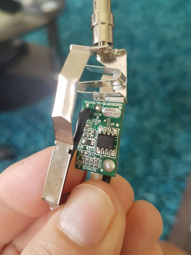
And here's the other side of the chip:
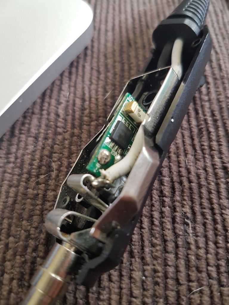
Also, specs on the charger indicate input voltage of '13V/26V' - the '/' seems to indicate 'or' to me, not a range of 13v-26v. Does this seem right? Or would any input voltage in the range 13-26v be sufficient? Reason being, I'm not yet sure how stable the output voltage of the Drok regulator is going to be under load and with declining input voltage.