
Hi everyone.
Let me describe the modification of Mavic Mini that I made during this winter, for which I already received requests from people who visited my introduction thread.
The main purpose of the mod was to make MM more resistant to wind, and consequentally less inclined to fly away in certain weather conditions. At this point, I think every Mini owner should be well aware of this problem. I believe I achieved some success in this regard, but the level of improvement is very hard to assess without a wind tunnel, where the wind is unidirectional, and the speed of it is adjustable and precisely known at any moment.
Initially, I thought I would be able to get the needed numbers for analysis by comparing the mean-maximum speed of the drone before and after the mod. Unfortunately, after many tries I didn't register any meaningful difference, the speed maxed in all configurations at around 29 mph. At this point I am inclined to believe DJI has capped the maximum speed of the Mini in software, relying on GPS data. Because of this, I cannot provide any hard, verifiable data which would back my claim of improvement. However, I have flown both original and modified Mini when UAV forecast was showing 15mph wind, and noticed this: while the maximum speed of the drone varied between 28 and 30 mph in both configurations (always drifting towards 29mph, as if PID-regulated), the modded Mini was significantly faster, up to +6 mph, when flying against the wind. Of course, these tests were months apart, taken at different temperatures, cloud cover etc., so please take them for what they are. They are not scientific.
Here is an attempt to summarize the pros and cons of this mod:
+ Better wind resistance -- improved aerodynamics and frame rigidity (hard to quantify, see above)
+ Longer flight time -- up to 32 min measured on stock battery, due to 12g weight reduction and improved airflow
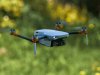
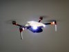
+ Improved low light visibility -- 2 front-mounted 200mW LEDs
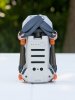
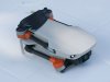
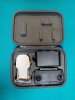
+ Retains foldability and compactness
+ Unique look (and bragging rights).
- Very hard and time consuming to do properly, even for an experienced modeler
- Voids the warranty
- Requires a CNC milling machine
- Potentially makes crashes more damaging to framebase by eliminating arm flexing (not tested)
Disclaimer: here I assume that people who would attempt this mod are quite familiar with tools and know how to disassemble the Mini without damaging it. And, in general, realize what they are getting themselves into. If anything goes wrong (a lot might!) I am not the one to blame.
If you are still interested, please read on...
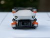
Take a look at the Mini in its original form. It is a well-engineered machine as is, rigorously tested by DJI, and they obviously have much better means to ensure it performs up to their quality standards, which are quite high. Can we modelers possibly do better then them? I think yes, sometimes. If you have your Mini at hand, please unfold it and look it in the eye (pardon, camera). This is the side which faces the wind. In my opinion, it doesn't look very aerodynamic. The overall area against which the wind pushes the Mini away from you, the pilot, is too broad mostly because the arms are too thick. The problem is, they cannot be made thinner with the plastic DJI chose, because they would become too flexible. Too much flexing in the arms would severely impede flight characteristics, vibrations would increase and become unpredictable, and the IMU would have to work much harder to compensate for changing geometry. DJI could have used a different material for arms, but that, in turn, would increase either the weight of the drone or manufacturing costs to unacceptable levels.
Thankfully, we modelers are not restricted much by material considerations. So the first obvious area of improvement, to me, was the arms. To make the new ones, I used high quality Japan-made woven carbon fiber tubes 7mm in diameter. Not that I chose this specific size deliberately, they just happened to reside in one of my toolboxes since ancient times. They have a round cross-section which is by itself an advantage (aerodynamically speaking) over almost rectangular cross-section of Mini original arms, and they are also about 2 times thinner. Which means less resistance to both wind and prop wash, thus improving the efficiency of the propulsion system as well.
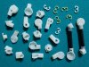
After the tubes were selected, I had to design motor mounts and pivots, and that was a nightmare. I can't tell how many times I had to revise and rebuild the whole thing from scratch. One of the photos I attached to this post, that shows some of the discarded parts which were all tested in flight and found to be inadequate in some way or the other, will give you an idea. I didn't include the parts which were discarded straight away because of some defect. Next I will try to describe some of the considerations and problems I encountered.
First of all, my material of choice for all plastic parts was nylon. It is very strong, retains its shape very well even when thin-walled, is relatively thermostable (motors could get hot enough to melt PVC, for instance) and most importantly, I had lots of nylon slabs laying around in my workshop. Unfortunately, it is also a very tricky material. It is milling-unfriendly, and sanding-unfriendly (and painting-unfriendly, as it turned out later). When cutting nylon with a CNC, the endmill has to be very sharp at all times, or the dimensions could end up way off. I only have a hobby-grade inexpensive 3-axis milling machine, and almost each part had to be made with several consequent setups (like this: cut a block with known dimensions, secure one side in angled vises, adjust angle, measure, cut, secure another side, adjust angle, measure, cut, secure third side, adjust angle, measure, cut, find the dimensions are off because the endmill dulled, discard, begin from scratch etc.)
Secondly, concerning pivots, which have to sit tight in sockets within Mini's original plastic frame and rotate freely without damaging the frame. Sometimes I think DJI deliberately attempted to make the frame un-moddable (which might be not far from the truth). No straight lines, odd angles, unexpected curvatures everywhere. In short, impossible to measure with a ruler or calipers. No matter how hard I tried to get the dimensions right, I always ended up using a Dremel and sandpaper afterwards. As I mentioned before, hardened nylon resists sanding very well, so it is quite a tedious and frustrating work. An unfortunate consequence of it, I can't provide any final dimensions here because, frankly, I don't know them myself. Please rely on photos which I tried to make as descriptive as possible.
Here is some info which concerns things not obvious from the photos, and some other things which are very obvious and are likely to raise a question.
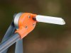
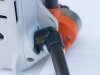
The front motor mount holds antenna frame which doubles as landing support. The frame is secured in the groove of the mount by a single screw. That screw, if metallic, needs to be as far away from the actual antenna as possible. I made the frame from a piece of fiberglass, glued antenna inside with double-sided tape and put a piece of shrink wrap tube over it. It is important to use only fully dielectric and radio-transparent materials around antenna. Ideally, it should be either completely sealed from moisture, or the opposite, be open to fresh air enough so that moisture can evaporate fast. For the frame, fiberglass should be clean without any copper traces left, carbon fiber must be avoided altogether. I found that black heat shrink tube reduces the range (maybe because it has carbon particles as coloring?), hence mine are currently white. Performance over looks!
The front pivot. This one is particularly troublesome to get the dimensions right. I used the original pivot spring mechanism within my nylon frame. The mechanism is quite strong, so be careful that it does not damage the original frame when inserted or pulled off. Pay attention to the shape of the front portion of the pivot socket where the front arm rests in unfolded position. It is about 3 degrees off vertical, which might not be obvious at first glance. If the shape of the pivot doesn't match the socket in this position, the frame will get deformed by the pressure of the arm and you will end up with asymmetrical Mini (which will fly asymmetrically, too, if at all.)
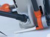
For the rear pivot, I did not use the original spring-loaded mechanism because it provides only two stops 180 degrees apart, and my rear arms needed to rotate about 205 degrees from folded to unfolded position. Actually, I did not want to use them anyway because a pair of them weighs 5.5 grams! They absolutely don't need to be this heavy. So I devised my own, completely made of nylon, which are supported by a nylon clip running in a groove in the pivot cylinder. That nylon clip acts as a (pretty weak) spring, supporting the arms at takeoffs and landings. A tooth prevents the rear arms from rotating past high point. During flight, thrust from motors naturally prevents the rear arms from folding. My pivots weigh 1.4 g together with clips, thus saving more than 4 grams on rear pivots alone. Not good, DJI!
The rear motor mount. Oh, these angles... 22.5 degrees off motor rotating plane, if I remember correctly, same as the rear arm itself off the pivot.
I need to emphasize that all linear dimensions and angles need to exactly mirror each other on the left and right side, otherwise the drone will not fly straight and will become almost useless as a videographic tool. The CG of the drone (with the battery inserted and gimbal guard taken off!) should be right at the centre between all four motors.
The substance I used to glue mounts and pivots to carbon tubes is called "J-B Plastic Bonder High Strength Structural Adhesive". It has a 15 minutes cure time, enough to make sure the parts being glued are properly aligned, and it stays a bit flexible after curing (unlike most epoxies) so it will not break in any crash. Highly recommended.
As for the front LEDs, this is the easiest part. There are pockets on the frame where front obstacle avoidance sensors should have been (but are absent on the Mini), covered with a sticky black pieces of plastic. Remove them. Take a sticky LED strip, put a plastic piece you just removed on it so that it covers a single diode and use scissors to cut it from the strip, following the contour of the plastic piece. Repeat with another diode, using the second plastic piece. Solder two tiniest insulated wires you can find to each of them, then glue them to the frame exactly where you removed the black plastic pieces from. Solder them in parallel, so that you have only two wires to deal with -- it is easier and saves weight. These two wires go to the back to ESC cluster PCB, which on top has a free pad labeled "3V6". This is where LEDs are powered from. A free ground pad is also there, on the other side of the screw that supports the IMU. I don't think I have to explain the rest... It's pretty easy, really.
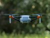
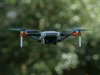
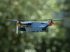
Finally, I would like to explain why I decided to rotate rear arms so far upward, compared to original Mini. The simple answer -- it flies a bit better. As to why, I believe the main reason is that in such configuration neither prop is in others propwash, which reduces turbulence and noise, and improves efficiency. When rear props are lower than the front ones, and the drone flies forward, the wash from the front propellers is shifted backwards by the wind and disturbs the airflow over the rear ones, making them less efficient and more noisy. This is noticeable only if you know what you are looking for, definitely nothing major (all Mavics have such configuration and fly well), but why not try to make good things even better if we can? Another advantage of my configuration over the original, is that it can take off where the original Mini can't: where there's short grass or something that might entangle the rear props if they are too close to the ground.
I can't cover everything about this mod in a single post (it is already too long!), but I will try to answer questions if there are any. Thanks.
Let me describe the modification of Mavic Mini that I made during this winter, for which I already received requests from people who visited my introduction thread.
The main purpose of the mod was to make MM more resistant to wind, and consequentally less inclined to fly away in certain weather conditions. At this point, I think every Mini owner should be well aware of this problem. I believe I achieved some success in this regard, but the level of improvement is very hard to assess without a wind tunnel, where the wind is unidirectional, and the speed of it is adjustable and precisely known at any moment.
Initially, I thought I would be able to get the needed numbers for analysis by comparing the mean-maximum speed of the drone before and after the mod. Unfortunately, after many tries I didn't register any meaningful difference, the speed maxed in all configurations at around 29 mph. At this point I am inclined to believe DJI has capped the maximum speed of the Mini in software, relying on GPS data. Because of this, I cannot provide any hard, verifiable data which would back my claim of improvement. However, I have flown both original and modified Mini when UAV forecast was showing 15mph wind, and noticed this: while the maximum speed of the drone varied between 28 and 30 mph in both configurations (always drifting towards 29mph, as if PID-regulated), the modded Mini was significantly faster, up to +6 mph, when flying against the wind. Of course, these tests were months apart, taken at different temperatures, cloud cover etc., so please take them for what they are. They are not scientific.
Here is an attempt to summarize the pros and cons of this mod:
+ Better wind resistance -- improved aerodynamics and frame rigidity (hard to quantify, see above)
+ Longer flight time -- up to 32 min measured on stock battery, due to 12g weight reduction and improved airflow
+ Improved low light visibility -- 2 front-mounted 200mW LEDs
+ Retains foldability and compactness
+ Unique look (and bragging rights).
- Very hard and time consuming to do properly, even for an experienced modeler
- Voids the warranty
- Requires a CNC milling machine
- Potentially makes crashes more damaging to framebase by eliminating arm flexing (not tested)
Disclaimer: here I assume that people who would attempt this mod are quite familiar with tools and know how to disassemble the Mini without damaging it. And, in general, realize what they are getting themselves into. If anything goes wrong (a lot might!) I am not the one to blame.
If you are still interested, please read on...
Take a look at the Mini in its original form. It is a well-engineered machine as is, rigorously tested by DJI, and they obviously have much better means to ensure it performs up to their quality standards, which are quite high. Can we modelers possibly do better then them? I think yes, sometimes. If you have your Mini at hand, please unfold it and look it in the eye (pardon, camera). This is the side which faces the wind. In my opinion, it doesn't look very aerodynamic. The overall area against which the wind pushes the Mini away from you, the pilot, is too broad mostly because the arms are too thick. The problem is, they cannot be made thinner with the plastic DJI chose, because they would become too flexible. Too much flexing in the arms would severely impede flight characteristics, vibrations would increase and become unpredictable, and the IMU would have to work much harder to compensate for changing geometry. DJI could have used a different material for arms, but that, in turn, would increase either the weight of the drone or manufacturing costs to unacceptable levels.
Thankfully, we modelers are not restricted much by material considerations. So the first obvious area of improvement, to me, was the arms. To make the new ones, I used high quality Japan-made woven carbon fiber tubes 7mm in diameter. Not that I chose this specific size deliberately, they just happened to reside in one of my toolboxes since ancient times. They have a round cross-section which is by itself an advantage (aerodynamically speaking) over almost rectangular cross-section of Mini original arms, and they are also about 2 times thinner. Which means less resistance to both wind and prop wash, thus improving the efficiency of the propulsion system as well.
After the tubes were selected, I had to design motor mounts and pivots, and that was a nightmare. I can't tell how many times I had to revise and rebuild the whole thing from scratch. One of the photos I attached to this post, that shows some of the discarded parts which were all tested in flight and found to be inadequate in some way or the other, will give you an idea. I didn't include the parts which were discarded straight away because of some defect. Next I will try to describe some of the considerations and problems I encountered.
First of all, my material of choice for all plastic parts was nylon. It is very strong, retains its shape very well even when thin-walled, is relatively thermostable (motors could get hot enough to melt PVC, for instance) and most importantly, I had lots of nylon slabs laying around in my workshop. Unfortunately, it is also a very tricky material. It is milling-unfriendly, and sanding-unfriendly (and painting-unfriendly, as it turned out later). When cutting nylon with a CNC, the endmill has to be very sharp at all times, or the dimensions could end up way off. I only have a hobby-grade inexpensive 3-axis milling machine, and almost each part had to be made with several consequent setups (like this: cut a block with known dimensions, secure one side in angled vises, adjust angle, measure, cut, secure another side, adjust angle, measure, cut, secure third side, adjust angle, measure, cut, find the dimensions are off because the endmill dulled, discard, begin from scratch etc.)
Secondly, concerning pivots, which have to sit tight in sockets within Mini's original plastic frame and rotate freely without damaging the frame. Sometimes I think DJI deliberately attempted to make the frame un-moddable (which might be not far from the truth). No straight lines, odd angles, unexpected curvatures everywhere. In short, impossible to measure with a ruler or calipers. No matter how hard I tried to get the dimensions right, I always ended up using a Dremel and sandpaper afterwards. As I mentioned before, hardened nylon resists sanding very well, so it is quite a tedious and frustrating work. An unfortunate consequence of it, I can't provide any final dimensions here because, frankly, I don't know them myself. Please rely on photos which I tried to make as descriptive as possible.
Here is some info which concerns things not obvious from the photos, and some other things which are very obvious and are likely to raise a question.
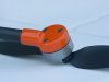
The front motor mount holds antenna frame which doubles as landing support. The frame is secured in the groove of the mount by a single screw. That screw, if metallic, needs to be as far away from the actual antenna as possible. I made the frame from a piece of fiberglass, glued antenna inside with double-sided tape and put a piece of shrink wrap tube over it. It is important to use only fully dielectric and radio-transparent materials around antenna. Ideally, it should be either completely sealed from moisture, or the opposite, be open to fresh air enough so that moisture can evaporate fast. For the frame, fiberglass should be clean without any copper traces left, carbon fiber must be avoided altogether. I found that black heat shrink tube reduces the range (maybe because it has carbon particles as coloring?), hence mine are currently white. Performance over looks!
The front pivot. This one is particularly troublesome to get the dimensions right. I used the original pivot spring mechanism within my nylon frame. The mechanism is quite strong, so be careful that it does not damage the original frame when inserted or pulled off. Pay attention to the shape of the front portion of the pivot socket where the front arm rests in unfolded position. It is about 3 degrees off vertical, which might not be obvious at first glance. If the shape of the pivot doesn't match the socket in this position, the frame will get deformed by the pressure of the arm and you will end up with asymmetrical Mini (which will fly asymmetrically, too, if at all.)
For the rear pivot, I did not use the original spring-loaded mechanism because it provides only two stops 180 degrees apart, and my rear arms needed to rotate about 205 degrees from folded to unfolded position. Actually, I did not want to use them anyway because a pair of them weighs 5.5 grams! They absolutely don't need to be this heavy. So I devised my own, completely made of nylon, which are supported by a nylon clip running in a groove in the pivot cylinder. That nylon clip acts as a (pretty weak) spring, supporting the arms at takeoffs and landings. A tooth prevents the rear arms from rotating past high point. During flight, thrust from motors naturally prevents the rear arms from folding. My pivots weigh 1.4 g together with clips, thus saving more than 4 grams on rear pivots alone. Not good, DJI!
The rear motor mount. Oh, these angles... 22.5 degrees off motor rotating plane, if I remember correctly, same as the rear arm itself off the pivot.
I need to emphasize that all linear dimensions and angles need to exactly mirror each other on the left and right side, otherwise the drone will not fly straight and will become almost useless as a videographic tool. The CG of the drone (with the battery inserted and gimbal guard taken off!) should be right at the centre between all four motors.
The substance I used to glue mounts and pivots to carbon tubes is called "J-B Plastic Bonder High Strength Structural Adhesive". It has a 15 minutes cure time, enough to make sure the parts being glued are properly aligned, and it stays a bit flexible after curing (unlike most epoxies) so it will not break in any crash. Highly recommended.
As for the front LEDs, this is the easiest part. There are pockets on the frame where front obstacle avoidance sensors should have been (but are absent on the Mini), covered with a sticky black pieces of plastic. Remove them. Take a sticky LED strip, put a plastic piece you just removed on it so that it covers a single diode and use scissors to cut it from the strip, following the contour of the plastic piece. Repeat with another diode, using the second plastic piece. Solder two tiniest insulated wires you can find to each of them, then glue them to the frame exactly where you removed the black plastic pieces from. Solder them in parallel, so that you have only two wires to deal with -- it is easier and saves weight. These two wires go to the back to ESC cluster PCB, which on top has a free pad labeled "3V6". This is where LEDs are powered from. A free ground pad is also there, on the other side of the screw that supports the IMU. I don't think I have to explain the rest... It's pretty easy, really.
Finally, I would like to explain why I decided to rotate rear arms so far upward, compared to original Mini. The simple answer -- it flies a bit better. As to why, I believe the main reason is that in such configuration neither prop is in others propwash, which reduces turbulence and noise, and improves efficiency. When rear props are lower than the front ones, and the drone flies forward, the wash from the front propellers is shifted backwards by the wind and disturbs the airflow over the rear ones, making them less efficient and more noisy. This is noticeable only if you know what you are looking for, definitely nothing major (all Mavics have such configuration and fly well), but why not try to make good things even better if we can? Another advantage of my configuration over the original, is that it can take off where the original Mini can't: where there's short grass or something that might entangle the rear props if they are too close to the ground.
I can't cover everything about this mod in a single post (it is already too long!), but I will try to answer questions if there are any. Thanks.
Attachments
-
 mm_assortment.jpg219.8 KB · Views: 719
 -
 mm_back.jpg65.5 KB · Views: 728
 -
 mm_folded_bottom.jpg88 KB · Views: 704
 -
 mm_folded_front.jpg62.7 KB · Views: 683
 -
 mm_folded_general.jpg62.3 KB · Views: 671
 -
 mm_front.jpg67 KB · Views: 690
 -
 mm_front_motor_mount.jpg98.3 KB · Views: 678
 -
 mm_inflight_day.jpg75.4 KB · Views: 700
 -
 mm_inflight_night.jpg38.3 KB · Views: 697
 -
 mm_packed.jpg170.5 KB · Views: 653
 -
 mm_rear_motor_mount.jpg60.6 KB · Views: 615
 -
 mm_rear_pivot.jpg66.9 KB · Views: 608
 -
 mm_rear_pivot2.jpg82.6 KB · Views: 610
 -
 mm_side.jpg71.7 KB · Views: 640


 SICK ? I hope you don’t have the virus... Better get some medical attention!!