DJI Mavic, Air and Mini Drones
Friendly, Helpful & Knowledgeable Community
Join Us Now

Alientech Duo II

Actually just went out 14,451’ on that Omni after swapping the qma connectors (had to return due to battery, not signal). Looks like I’ve got a bad qma connector! Somewhat relieved.
 
  • Like
Reactions: DroneToJoy
Alrighty, I've settled (for now) on my desired remote end-state. Went with RP-SMA ends to replace the super skinny QMA connectors and in the process I've removed an adapter (qma > sma) which is always a welcome change. I added some super basic, no-name, no-brand 3" whips which yielded full bars a mile out so these will be great for when I'm not using an amplified solution.

Can't wait to get the Sunhans 2.4 and 5.8 amps added to this with the 4Hawks Raptor SR - now that I know there's a dedicated antenna for each signal.

Sorry to everyone in the thread for the hijack. I hope some of the info discovered regarding the Air 2/Mini 2 remote is helpful to others who want to mod. To be perfectly honest, if I didn't want to use my car and house antenna setups which require removable antennas via rp-sma I'd be 100% absolutely content with the shockingly powerful range the stock antenna provides. Wow...I still can't believe it.
 

Attachments

  • IMG_3284.jpg
    IMG_3284.jpg
    1.9 MB · Views: 53
  • IMG_3285.jpg
    IMG_3285.jpg
    2.1 MB · Views: 49
  • IMG_3286.jpg
    IMG_3286.jpg
    1.8 MB · Views: 50
Opened up the remote and confirmed the leads:


W = 2.4 ghz antenna
B = 5.8 ghz antenna
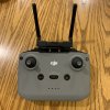
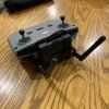
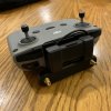
Very valuable information! Looking further at some RC teardown Chinese movie I found that Black 5.8GHz seems connected to the left stock antenna and the White 2.4GHz on the right side, looking from the pilot view. I just ordered two Yagi’s for 2.4 and 5.8 respectively. I intend to cut them and install the 5.8G element on the left and 2.4 Yagi on the right, thus having a dual band Yagi setup.
 
  • Like
Reactions: alexdrago87
I did some more testing and finally got a 5.8ghz amp as well. It may not be as I had originally thought but there’s still something going on I can’t figure out.

The “W” antenna is what is most important from what I’ve found. I have zero idea at this point what the “B” antenna does or what it’s for. It may still be related to 5.8 ghz but I only have a single amp for that band to test with so I can’t dive deeper.

“W” is the antenna that I needed to use for my long range 5.8 ghz test flight - so this means it’s not just for 2.4 ghz. Now, what I don’t know is if the “B” antenna does anything to benefit the 5.8 ghz band while flying long range. I’d need another amp and 5ghz antenna to test.

I did another 14k long distance test on 2.4 ghz today and the 2.4 ghz amp and antenna, plugged into “B” did nothing at all for improving for reducing the quality of the video or overall remote control connection. I have ZERO idea what the “B” antenna is for.

I would love if someone smarter than I could enlighten me. :)
 
For example, in LTE routers one can find a multiband primary (RX/TX) and a multiband secondary antenna (receive only). The two antennas are orthogonal and needed for the differential receive.
I have to say I was bit surprised to hear that instead of such a differential setup, the RC might use only one antenna per band.
Could you please reconfirm what exactly you have discovered during your experiments? Did you assume that W is 2.4G (single band) and the other must have been 5.8 because your 2.4 amplifier worked with W? Did I understand correctly, that now a new 5.8G amplifier also needed W?
In such case, W would be rather the multiband RX/Tx antenna and B - the secondary receiving antenna, helping RC to mitigate phase effects related to changing distance and/or radio waves’ reflections.
 
Last edited:
Ok, folks had my first test flight which Im trying to out into a video for viewing but of course Im still learning all about post video production!!!!

Meantime just wanted to update you that the flight was amongst some thick trees in the neighbourhood on a mountain side and with the original RC for my Mini 2, I managed around 300-600m distance in a certain direction before RC cut off (there really is no direct line of sight but through trees/foliage.) For the same flight using Alientech I could get to 900m without RC disconnect and managed a round trip to parts I could not fly to downhill/out of complete visual line of sight and over urban density/forrest to around 1000m - before the RC disconnected with the Alientech booster powered on. On review I also think I was pointing the RC in the wrong direction as this was also the first time I was using the new 1.2.2 fly app, so was not yet sure of how the compass/positioning worked.

Although I wanted flawless flight, taking these circumstances into account i think the booster did a good job. I'm still trialing more and will update.
 
  • Like
Reactions: cstout and Oldi001
For example, in LTE routers one can find a multiband primary (RX/TX) and a multiband secondary antenna (receive only). The two antennas are orthogonal and needed for the differential receive.
I have to say I was bit surprised to hear that instead of such a differential setup, the RC might use only one antenna per band.
Could you please reconfirm what exactly you have discovered during your experiments? Did you assume that W is 2.4G (single band) and the other must have been 5.8 because your 2.4 amplifier worked with W? Did I understand correctly, that now a new 5.8G amplifier also needed W?
In such case, W would be rather the multiband RX/Tx antenna and B - the secondary receiving antenna, helping RC to mitigate phase effects related to changing distance and/or radio waves’ reflections.

Yes, you're correct and my assumptions were incorrect after flying with a 5.8 ghz amp and omnidirectional antenna. The antenna needed to be connected to "W" in order to have a successful long range flight on this band. So, like you said, I now believe that "W" is both 2.4 and 5.8.

What I'm still trying to figure out is the actual purpose of the "B" antenna as in all of my long range flight tests (2.4 only and 5.8 only, not dual band) I've seen no performance or signal difference (even in the db reading on the connection stats menu) with "B" connected or disconnected.
 
All clear - thanks for sharing. I just ordered in UK an IMMERSIONRC RF POWER METER v2 and intend to continue your research. (It may take several weeks to deliver though.) I expect the B antenna to be the secondary receiving antenna (on 95%). Remaining 5% of probability I leave for some weird ideas, like e.g. broadcasting electronic ID or similar..
IMHO the purpose of such secondary receiving antenna would be to prevent temporary phaseouts, when the drone is moving. Not sure if this would be visible in dB readouts in static situations.
 
Last edited:
  • Like
Reactions: cstout
This photo may be of benefit. It's from DJI's filing with the FCC for approval of the Mavic Air 2 controller. It clearly shows that the white antenna is for both receive and transmit on both 2.4 and 5.8 GHz while the black antenna is a 2.4/5.8GHz receive only antenna.

In the filing, DJI states that at 2.4 GHz the antenna has 3 dBi gain (barely more than a dipole) and at 5.8 GHz the antenna has 4 dBi gain.

1610023361825.png
 
This photo may be of benefit. It's from DJI's filing with the FCC for approval of the Mavic Air 2 controller. It clearly shows that the white antenna is for both receive and transmit on both 2.4 and 5.8 GHz while the black antenna is a 2.4/5.8GHz receive only antenna.

In the filing, DJI states that at 2.4 GHz the antenna has 3 dBi gain (barely more than a dipole) and at 5.8 GHz the antenna has 4 dBi gain.

View attachment 121092
Thanks for sharing this. I just got my omnidirectional 5.8ghz antenna and connected it to my 5.8 amp and to the “W” connection and flew out 11,800 ft before signal loss. Nothing connected to the “B” connection. I was hoping I’d see something different flying on 5.8 only with one antenna, but at this point I’m still at a loss. No idea what the “B” connection is good for. Even if it is “receive only” I’m not sure what it’s receiving if the “W” connection is sending and receiving all necessary flight controls and video data.
 
  • Like
Reactions: MathAddict
Thanks for sharing this. I just got my omnidirectional 5.8ghz antenna and connected it to my 5.8 amp and to the “W” connection and flew out 11,800 ft before signal loss. Nothing connected to the “B” connection. I was hoping I’d see something different flying on 5.8 only with one antenna, but at this point I’m still at a loss. No idea what the “B” connection is good for. Even if it is “receive only” I’m not sure what it’s receiving if the “W” connection is sending and receiving all necessary flight controls and video data.

1. Have you tried the omnidirectional antenna, on the exact same route, without the amplifier?

2. What make and model amplifier do you have?

Best,

Jim
 
1. Have you tried the omnidirectional antenna, on the exact same route, without the amplifier?

2. What make and model amplifier do you have?

Best,

Jim
Hi Jim,

Just ran another test flight. 2x 2.4 omnis plugged in without amps only got me 1600’ before signal loss. Plugged in amps and went out to 14,100’. Signal was fine the whole time and while I was out at that distance I unplugged the “B” antenna and there was absolutely no change in signal strength, quality of the video feed, or any other perceived difference. The map was still fluidly updating the position, and everything was working great.

The only test I haven’t done yet which may be unnecessary is trying to fly using the dual band setting with one 2.4 and one 5.8 antenna plugged in. I doubt that would be any different though since it seems that all necessary transmission occurs on the “W” antenna.

Edit: I forgot to note I’m using 2x RF LINX 2.4 GHz 1W amps that were from my long range Phantom 4 setup. The omnidirectional antennas are 2x 9dB L-Com HG2409U.

The 5.8 GHz antenna I just received is a low cost 8.5 dB omni from data-alliance and it performed great on the RF LINX 5.8 GHz amp I have. Only complaint is the antennas connector is N female instead of N male so I had to use a Male-Male adapter to connect it to my magnetic antenna base. Makes it look like a light saber now. Haha
 
I’ve got a custom Raptor SR coming my way soon that I’m excited to test out. I’ll be sure to report back to see how it compares to the stock antenna.

Anybody make any new discoveries with the “B” antenna connection?

@Oldi001 I’m eagerly awaiting the results of your RF meter tests! Hopefully that will give some insight to whether or not anything is actually sending/receiving on that connection.
The RF Power meter v2 came. It seems smaller than in the pictures and makes to me an impression of being more like a tester (or a toy) rather than a real meter. I hope I will learn how to apply, interpret (and trust) the results with time.
Now to the results: only the right RC antenna (looking from the pilot’s view) is transmitting on 2.4 and 5.8Ghz. The (uncalibrated) meter shown about 3 dBm of peak power. The antenna on the left is the differential receiving antenna. This was already shown in the excellent picture posted above by @MathAddict .
On the drone side, the dual band transmit antennas are in the front left and front right legs. The meter shown intermittent results, like if the drone was switching between its left or right antennas... depending e.g. on its orientation towards RC or other factors.

Now to the Alientech duo ii: Yes it has 2.4GHz antenna panel on one side and the 5.8 panel on the other. However if you look carefully to the circuit board pictures, you could also notice that both RC cable signals are effectively mixed to a single input node. Split for 2.4 and 5.8 is being done further in the circuit. Thus I suspect the order of the input cables does not mater, when installing the Alientech on RC.
 
Last edited:
Welp, stock antenna is removed, Raptor SR is in, and I’ve got to say...I’m extremely disappointed. This highly directional antenna got almost the same distance as my 3” free omnidirectional antenna I took off an old PC wireless card. For $120 I had much, much higher expectations. The Raptor gave me an additional 50’ (yeah, that’s all) and the flying experience was much less enjoyable because I had to hold the remote in a perfectly straight line toward the Mini. With the little omni’s I can hold it pretty carelessly and still have the same signal.

With that said, here are some stats:
Stock antenna, no modification: 13,023’ (could have gone further but returned for battery)

Antennas removed: 2,650’

3” free junk omnidirectional antenna: 9,450’

$120 Raptor SR (no amp): 9,489’
Raptor with 1W RF Linx amp: 15,224’

Long story, short...I’m sad I spent the money on a large directional antenna that doesn’t perform as well as the stock antenna. If you ask me if it’s worth modifying the Mini 2 controller, I have to say it really isn’t. The primary reason I did, and will keep the mod, is so I could have an SMA jack to connect to magnetic omni antennas for on top of my car. If I didn’t need to be able to connect those then I wouldn’t have changed from stock.

Also, all of my tests were with only the W antenna connector plugged in. Plugging in B did not cause any improvement or impact to the distance tests I did. As far as I’m concerned, the “B” connector is not required for normal or modified operation.
 
As Raptor SR is passive only, I decided to go with Alientech Duo II, which arrived very fast. Regrettably my first assembly attempt was not very successful. Actually I find two things to be a major pain in the rear: opening the RC and connecting antenna cables to the board.
I managed to overcome both challenges, however during the final assembly one of the new antenna cables got crushed between two halves of the RC case. As the cable could be defective now, I decided to order new pigtails from Alientech. I wish Alientech wrote some good manual with pictures, mentioning optimal cable layout and e.g. purpose of each screw type.
 
Thanks to @armyndharis quality pictures I noticed that the Alientech antenna cables should not go straightforward as shown in their video. They should turn right instead. I was bit worried that the cables might now block the important “go home” button, so I decided to pass them just before the right joystick connector. Finally I completed the entire assembly ☺️ The RC still works after the installation of the Alientech booster. Snow storm prevented me from checking the CE range improvement though.
Edit: Made the test flight today. Reached 2500m in CE mode at 120m altitude. Suburban and forest terain. To give a context: The same RC with Yagi 2.4MHz gave me 2400m two weeks ago, in the same direction.
 
Last edited:
great discussion here,
The new remote on mini 2/air2 is fantastic.
I’ve compared the stock remote with smartcontroller, yes the stock remote outperform the smartcontroller, thats why I replace the SC antenna with alientech duo, the result? Fantastic!

but now I’m waiting the duo II, cannot wait for it :)

I’m using smartcontroller because with stock new remote on mini2/air2/s the distance limit is 11.11km only :)
 
Last edited:
  • Like
Reactions: sharkctx
Does anyone happen to know what size threads they put on the bottom of the alientech duo II? The threads that will allow it to mount to roof rack or stand?
 
Lycus Tech Mavic Air 3 Case

DJI Drone Deals

New Threads

Forum statistics

Threads
130,928
Messages
1,557,944
Members
159,930
Latest member
AASHIANAPC