


You are using an out of date browser. It may not display this or other websites correctly.
You should upgrade or use an alternative browser.
You should upgrade or use an alternative browser.
DJI RC (mini 3 with display) controller disassembly
- Thread starter MaximusCZ
- Start date


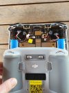
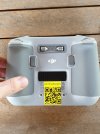
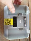
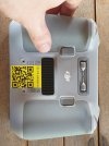
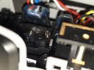
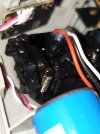
Okay, so I have it opened, but its really hard to measure. My measuring tool doesnt reach all the way down to plastic, so the result might be a bit off. I tried my best, and it seems the speaker is 5.86 cm off the side (C2 button side), and 4.45 cm off the top. Always measured from the outer edge of plastic of the "front" half. The bottom half gets a bit wider as you go "deeper down", again roughly measured to 3.6 mm. So maybe 6.22 cm from the edge of controller, 4.45 cm from top?Have you located the exact position inside the RC-Pro, to know where to drill a hole through the case to get to it, without tearing the case open? It's different than the Smart Controller, and it's well documented on the RC-N1. Just no clear tear down on the RC-Pro yet. This is the best I can figure out from the FCC filings.
View attachment 149174
The speaker itself is fairly big (1.2 cm diameter), so it will be fairly easy to hit, but the speakwr hole is only about a millimeter or two
I attached some pics with and without back. I tried my best to not move the camera, so maybe try interposing the images on top of each other, should give pretty accurate location of the speaker (covered by the yellow square tape)
Attachments
Last edited:
Category 5
Well-Known Member
- Joined
- Sep 16, 2018
- Messages
- 65
- Reactions
- 56
- Age
- 51
Interesting stuff. The tinkerer in me wants a mini 3 even more now. It would be cool to make holes for two SMA ports on he top of the controller, and wire those to the internal connectors. Then you could just screw on any high gain antennas you wish. There are a ton available and depending on how "mobile" the operator needs to be there are some that are quite powerful, albeit bulky.
Category 5
Well-Known Member
- Joined
- Sep 16, 2018
- Messages
- 65
- Reactions
- 56
- Age
- 51
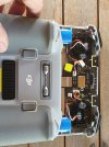
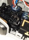
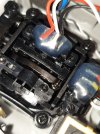
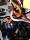
BTW, it looks like there might be pretty easy access to the control stick springs back there. A closer pic would help tell for sure, but if you want to firm them up you can just clip the spring length down a bit.
Ask and thou shalt receiveA closer pic would help tell for sure
Attachments
-
 20220604_175114.jpg1.3 MB · Views: 67
 -
 20220604_175102.jpg1.3 MB · Views: 66
 -
 20220604_175044.jpg1.2 MB · Views: 65
 -
 20220604_175124.jpg1.5 MB · Views: 61
 -
 20220604_175137.jpg2.7 MB · Views: 58
 -
 20220604_175147.jpg2.8 MB · Views: 54
 -
 20220604_175222.jpg1.2 MB · Views: 51
 -
 20220604_175243.jpg1.3 MB · Views: 64
Category 5
Well-Known Member
- Joined
- Sep 16, 2018
- Messages
- 65
- Reactions
- 56
- Age
- 51
Hmm. I only see two of the springs but they look like they could be shortened easily. You can use two flat pliers to bend up a loop at the new length. Use the new loop to connect the spring and clip off the spring above it. You'd have to take the screws and retaining piece out to see if there is easy access to the spring for the other direction. Spring loaded mechanisms are tricky to disassemble and re-assemble but that one doesn't look overly complex.
EDIT - It's possible the same spring is used for both directions (likely actually) so you could probably just shorten those two visible springs and achieve your goal.")
EDIT - It's possible the same spring is used for both directions (likely actually) so you could probably just shorten those two visible springs and achieve your goal.
Last edited:
yes, as you move left/right, the same spring gets lifted on the same side. Its 2 springs per whole joystick
Category 5
Well-Known Member
- Joined
- Sep 16, 2018
- Messages
- 65
- Reactions
- 56
- Age
- 51
yes, as you move left/right, the same spring gets lifted on the same side. Its 2 springs per whole joystick
Nice. Shouldn't be terribly hard to firm it up then. I'd start modestly with just a few coils at a time. Try one spring and see how much stiffer it gets and then use the same amount for the others. I'd go less than you think since it may become too firm after flying for a bit. Making them firmer should be easy, but you won't be able to go back the other way without replacing the springs.
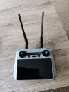
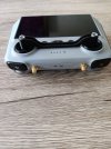
Hi, here is another modified RC.
Unfortunately I'm not getting too much improvement over stock antenna.
all test done at 120m height
original antenna in town 600m and in field 1400m
Now with "6dbi" antennas in town 750m and in field 1750m.
I also tried "8dbi" antenna which is longer but result is worst than 6dbi.
Any suggestions?
Thanks
Attachments
SpinItUp
Well-Known Member
That's some ugly antennae

If I understand correctly, dB indicates how directional antenna is. Higher number (with otherwise identical specs) would mean better transmission at correct angle, but worse transmission at incorrect orientation.Hi, here is another modified RC.
Unfortunately I'm not getting too much improvement over stock antenna.
all test done at 120m height
original antenna in town 600m and in field 1400m
Now with "6dbi" antennas in town 750m and in field 1750m.
I also tried "8dbi" antenna which is longer but result is worst than 6dbi.
Any suggestions?
Thanks
I think your biggest issue is impedance matching. The amplifier in the remote (that sends signal to antenna) is designed with that specific antennas impedance in mind. Fitting hugely different antenna would mean impedance mismatch, so a lot of energy sent to antenna is reflected back to amplifier, instead of emitted into space.
Your best bet would be either of those:
- finding antenna with higher dB than original while maintaining similar impedance. That way you would have to be more careful to aim the remote precisely, but your range would improve.
- modifying the amplifier to accommodate your new antennas impedance.
Kuykenstuff
New Member
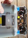
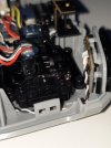
So since I couldn't find a video to disassemble to DJI RC, I said to myself "how hard can it be anyways" and disassembled it.
I got you, man! I followed this thread, replaced my control stick module, and filmed it to share with y'all. It's not a full tear down, but here's what I did:
albertino78
Well-Known Member
Ho everybody!
Last weekend I’ve had a “little incident”….

So I decided to disassemble the controller and finally I’ve resolved…..

Last weekend I’ve had a “little incident”….
So I decided to disassemble the controller and finally I’ve resolved…..
NightFlightAlright
Well-Known Member
Unfortunately I'm not getting too much improvement over stock antenna.
all test done at 120m height
original antenna in town 600m and in field 1400m
Now with "6dbi" antennas in town 750m and in field 1750m.
I also tried "8dbi" antenna which is longer but result is worst than 6dbi.
Any suggestions?
Thanks
Improving from 1400m to 1750m is surprisingly good for just changing the antenna from 3dbi to 6dbi. That's a 25% distance improvement, and while 6dbi sounds like double 3dbi, it's not that simple.
There's a couple of things that you might want to know about antennas:
First of all there's no free lunch. A passive (un-amplified) 6dbi antenna is not going to double your range by ANY stretch of the imagination. There could be some modest benefit increasing size and getting it farther away from the remote and into free air, and added directionality which I suspect is the biggest improvement. But the size needs to be appropriate for the wavelength, ie frequency.
Second, directional gain. Remember that signals decrease in amplitude by the square of the distance (inverse square law). An omnidirectional antenna radiates or receives equally in all directions. This is good where you have no way to orient the antenna in the direction it needs, but it's obviously less efficient because you have energy radiating directions that are unneeded. So for something like a 6 dbi antenna, it's going to be directional—that extra energy comes from somewhere, and it comes from the nulled direction—so, if you're not pointed correctly at the drone for your antenna's directionality, you're much more likely to lose contact.
Third, "db or not db, that is the question"... The internal antenna and the RC is a 3dbi antenna as I understand it. A 6dbi antenna is NOT going to double the effective strength or range. Doubling a 3dbi antenna would need (I think) a 12dbi to 15dbi antenna. Without amplification, that's going to have such a narrow beam, it's going to be hard to keep the controller pointed at it effectively.
Fourth, Signal polarization. Terrestrial Wi-Fi is most typically linear-vertically polarized. Looking at the photos of the internal antenna of the RC the antennas look like they are dual-horizontal+vertical. (some drones, and for instance FPV goggles are circularly polarized (CW or CCW)). For a vertically polarized signal if receive side is 45° off results in about a 3 db loss.
Fifth, impedance, the transmit and receive circuitry in the remote control is going to be designed for a specific impedance antenna, so any antennas that you yourself decide to modify it with, need to be of the same impedance as the circuit was designed for.
Sixth, the total TxRx system. It's not just the remote control after all, you also have the drone out there which has its own transmit and receive circuitry and its own transmit and receive antennas. I think some of the enterprise drones can have added Tx boost modules added (some of those drones are in the $15,000 + range...) For the consumer level Mavic/Mini etc, such an active mod is not just going to add weight, but also subtract from flight time, (not to mention questionable legality, your mileage may vary, different nations have different laws on that.)
---------
Your setup: those look like the kind of antennas that are just on a home router. If they are, then they're probably just vertically polarized. Orientation can have an effect. Same is true for your 8dbi antennas, no I suspect that you got worse range with the 8dbi because they were substantially more directional, (read: narrower beam) and the drone was slipping out of the beam.
Thank you for being adventurous, I helped me tear down my RC to fix a sticky tilt roller on the left side. Appreciate this tutorial.Add the RC1A/B antennae to it and it performs way better
A.A.Ron
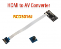
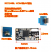
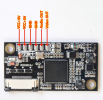
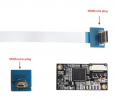
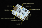
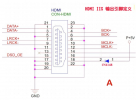
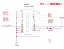
Where is the video signal port to the LCD panel? Is it using a ribbon cable?
I wonder if it is possible to add video out feature to the RC controller.
I found 2 PCB design on taobao that may work?
I wonder if it is possible to add video out feature to the RC controller.
I found 2 PCB design on taobao that may work?
Attachments
Last edited:
docmetzger
New Member
Thanks for sharing all the pictures!
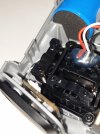
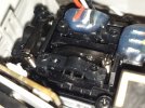
They encouraged me to disassemble my controller in order to change the direction of the gimbal pitch (left hand wheel) because from my intuition, I expected the gimbal to move down upon pushing the wheel to the right and lift up upon pulling to the left.
All I had to do was to swap the red and black wire on that wheel (see photo below, taken from this thread).

BTW: in a first try, I swapped the brown and the white pin on the central connector to the main board (after measuring the related change of resistance on these pins). But for some reason, this also deactivated both buttons on the bottom of the controller.

They encouraged me to disassemble my controller in order to change the direction of the gimbal pitch (left hand wheel) because from my intuition, I expected the gimbal to move down upon pushing the wheel to the right and lift up upon pulling to the left.
All I had to do was to swap the red and black wire on that wheel (see photo below, taken from this thread).
BTW: in a first try, I swapped the brown and the white pin on the central connector to the main board (after measuring the related change of resistance on these pins). But for some reason, this also deactivated both buttons on the bottom of the controller.
Add the RC1A/B antennae to it and it performs way better
In this video the creator explain how modify antennas.Add the RC1A/B antennae to it and it performs way better
GroovyGeek
Well-Known Member
That's not a very good video. The through holes for the SMA feedthroughs should be further out, so that the cable on the other side does not bump into the posts.In this video the creator explain how modify antennas.
I am getting very conflicting reports whether this mod makes one bit of difference. It looks pretty straightforward and these days you can buy dual band 8db antennas for under $10, but without a consensus hmwhether it does anything I will hold off.
Golfnjunkie
New Member
Awesome! I have a DJI 3mini pro, same controller, the RM330. The left thumb wheel isn't responding. What bit did you use to remove those screws? They look like the holes are threaded?Ill edit this post as I continue exploring
So since I couldn't find a video to disassemble to DJI RC, I said to myself "how hard can it be anyways" and disassembled it.
Here is first few photos:
If anyone wanna see anything specific, let me know before I close it again
So far:
4 screws total. 2 from bottom in the hole (visible), 2 under the glued rubber stick holder
Started from the bottom, under charging USB-C port, afterwards I think its the best place to start.
Used two dull dining knives to open. I tried plastic tools but it bends too much. Surprisingly few scars (if any) on the plastic of controller, its tough stuff.
Edit:
Edit2:

Similar threads
- Replies
- 5
- Views
- 2K
- Replies
- 7
- Views
- 4K
- Replies
- 3
- Views
- 7K
- Replies
- 1
- Views
- 3K


DJI Drone Deals
New Threads
-
-
Lost drone: possible crash due to lost signal?
- Started by fharrihill
- Replies: 3
-

-
 Last Week's Most Popular Topics (January 31, 2026)
- Started by msinger
- Replies: 0
-
 How to Protect and Extend the Life of your Equipment in 2026 (By Timothy Brazzel)
- Started by The Droning Company
- Replies: 2
Forum statistics