

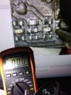
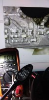
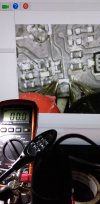
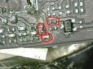
hello guys need help badly in determining multimeter ohmeter values of the marked resistors A, B and C as im suspecting these are my busted burnt resistors that i need replaced. thanks to the highly technical guys here who can check the smd resistor values. the other photos attached shows these resistors showing 00.0 reading and beeping in continuously in the continuity selector

You are using an out of date browser. It may not display this or other websites correctly.
You should upgrade or use an alternative browser.
You should upgrade or use an alternative browser.
need help on resistor values gimbal video section
- Thread starter commrus
- Start date


Yorkshire_Pud
Well-Known Member
Whilst they may be burnt, relying on values measured in situ if likely to be highly unreliable. You should AT LEAST isolate one end of the resistor, other wise you could be measuring the resistance across one or more parallel circuits let alone applying voltages across diodes and chips.
Unless someone has a blown main board I wouldn't want to go sticking meter probes onto a working board.
Do SMD resistors tend to burn out to a short circuit?
EDIT
It looks like you are using crocodile clips as probes, you could be touching something else whilst trying to get a measurement. I would suggest that if you do not have needle point probes then grip pins or sewing needles in the crocodile clip, check their probe to probe resistance, and then retake your measurements, not that they may be of much use.
Last edited:


thanks for the reply mate!Whilst they may be burnt, relying on values measured in situ if likely to be highly unreliable. You should AT LEAST isolate one end of the resistor, other wise you could be measuring the resistance across one or more parallel circuits let alone applying voltages across diodes and chips.
Unless someone has a blown main board I wouldn't want to go sticking meter probes onto a working board.
Do SMD resistors tend to burn out to a short circuit?
EDIT
It looks like you are using crocodile clips as probes, you could be touching something else whilst trying to get a measurement. I would suggest that if you do not have needle point probes then grip pins or sewing needles in the crocodile clip, check their probe to probe resistance, and then retake your measurements, not that they may be of much use.
no crocodile clips used here its a typical pointed tip of a multi meter and nothing is touching any components except the two ends and verified it either side several times. yes i agree it is not 100% reliable value however basing on board current value i what i need to be able to identify and replace a new resistor until it hits same value without powering up the drone yet.
the resistor burnt when a ground wire from the gimbal hit a component. the burnt resistors though burnt already at first were fully functional eventually the camera and gimbal gave in to a mulfunction. other than this trouble the drone flies perfectly smooth rth gps no problem. i am now in the process of fixing it and analyzing the section if someone could just provide me a reading on these components. i have a brand new camera gimbal set so its not really a problem.
just looking for someone techie enough who does electronics work on these stuff. more of a drone surgeon
db4476
Well-Known Member
Whilst they may be burnt, relying on values measured in situ if likely to be highly unreliable. You should AT LEAST isolate one end of the resistor, other wise you could be measuring the resistance across one or more parallel circuits let alone applying voltages across diodes and chips.
Unless someone has a blown main board I wouldn't want to go sticking meter probes onto a working board.
Do SMD resistors tend to burn out to a short circuit?
EDIT
It looks like you are using crocodile clips as probes, you could be touching something else whilst trying to get a measurement. I would suggest that if you do not have needle point probes then grip pins or sewing needles in the crocodile clip, check their probe to probe resistance, and then retake your measurements, not that they may be of much use.
db4476
Well-Known Member
Agreed, testing mounted components can be hit or miss though a resistor is usually the easiest to test. First check that there is no voltage supplied then check ohms.
Industry standard markings:
"Standard-tolerance SMD resistors use a 3-digit code to mark the resistance value on the part. The first two numbers will indicate the significant digits, and the third will be the multiplier. 'R' is used to indicate the position of a decimal point."
SMD resistor code calculator here:
Code calculator
Cheers!
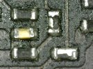
thanks for the interest to reply db4476! i love the people here in mavicpilots because many here are very friendly and helpful! dji uses in this section of circuit the smallest of its kind smd resistors and they have no labelsAgreed, testing mounted components can be hit or miss though a resistor is usually the easiest to test. First check that there is no voltage supplied then check ohms.
Industry standard markings:
"Standard-tolerance SMD resistors use a 3-digit code to mark the resistance value on the part. The first two numbers will indicate the significant digits, and the third will be the multiplier. 'R' is used to indicate the position of a decimal point."
SMD resistor code calculator here:
Code calculator
Cheers!
")
Dave Maine
Well-Known Member
- Joined
- Jan 27, 2018
- Messages
- 1,547
- Reactions
- 1,123
- Age
- 82
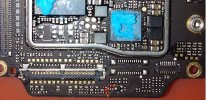
please check the images attached on this post as the resistors are badly burned with zero reading in ohmeter that makes them prime suspects at preliminary visual inspection including multimeter 0 resistance reading. this section of the camera gimbal is composed of smd capacitors and resistors only nothing else.Resisters are usually the last thing to fail. I wouldn’t change them unless I had verified all the other elements in the entire circuit.
Attachments
Dave Maine
Well-Known Member
- Joined
- Jan 27, 2018
- Messages
- 1,547
- Reactions
- 1,123
- Age
- 82
root cause 100%: micro negative fine wires from the ground hit that specific resistors when the lower shell was reinstalled. unless someone can give me a reading value of these onboard resistors as requested in my post above, i will not be able to fix it right away. all other section is 100% okay i have no problem and 100% no app errors relating to a board problem. all i need right now at this time are the only three resistors multimeter value reading. it will help if i found out the reading values of these three resistors so i can fix my drone asap. thats all i need for now. so if someone can give me a reading on these id be very happy and it will mean so much to me. thats all i need nothing more. only resistor onboard values on multimeter so if there are guys techie here who does electronics or drone surgery would be delighted. advance thanks to those who can give me these 3 resistor readings! thats all i need.Why are they burned? That will be the root cause.
Attachments

retiredNH
Well-Known Member
Am I the only one confused by the OP?
Is he trying to measure burned out resistors? (Can't...)
Is he trying to measure a load current through the burned out connections?
Does the OP have experience replacing/resoldering SMD components?
Seems to me the best help would be for someone to look at an existing good Air2s and read the values (by eye, not meter...)
you are correct you can measure a burned out resistor and the value will show 0.00 as indication 100% proof it is burned. you can test a burned resistor and the measure result is 0.00 because it is already burned so no load will show up but you can measure it 0 to up. replacing resoldering is not a problem 100% accuracy rating using electron magnifier and tools of the trade. i need someone who can measure a good proper working resistor labeled in the attached reading on their air2s so if you have an air2s techie can measure from your end the specified resistor placements on my photo and willing to help me then its a big contribution to me identifying the values of these resistors. need help only of good on board value of the resistors labeled A.B,C as indicated. thanks to those who can give honest direct answer.Am I the only one confused by the OP?
Is he trying to measure burned out resistors? (Can't...)
Is he trying to measure a load current through the burned out connections?
Does the OP have experience replacing/resoldering SMD components?
Seems to me the best help would be for someone to look at an existing good Air2s and read the values (by eye, not meter...)
Attachments
Last edited:
retiredNH
Well-Known Member
Now things are making sense! Maybe one of the more technically inclined than me will take a look under the cover and read the values.you are correct you can measure a burned out resistor and the value will show 0.00 as indication 100% proof it is burned. you can test a burned resistor and the measure result is 0.00 because it is already burned so no load will show up but you can measure it 0 to up. replacing resoldering is not a problem 100% accuracy rating using electron magnifier and tools of the trade. i need someone who can measure a good proper working resistor labeled in the attached reading on their air2s so if you have an air2s techie can measure from your end the specified resistor placements on my photo and willing to help me then its a big contribution to me identifying the values of these resistors. need help only of good on board value of the resistors labeled A.B,C as indicated. thanks to those who can give honest direct answer.
Good luck!
thank you so much for those sweet words my friend. i know there are lots of drone surgeons and techie here. It may just take time before they come across this post because most of them are too busy and highly professionally inclined. not many have time for small fry like me. lol!Now things are making sense! Maybe one of the more technically inclined than me will take a look under the cover and read the values.
Good luck!
BrianA
Well-Known Member
I've been in electronics for 40+ years and have extensive troubleshooting experience. I have never seen a resistor short (0 ohms on your meter). Are your sure those are resistors and not capacitors or you are reading across a parallel circuit? Usually when resistors get crisp like that, you will read a very high resistance and/or complete open. As others have said, the only way to check the individual component is to isolate a minimum of one end of it. If that can't be done, then the the entire component would have to be removed and tested. Maybe not worth it and just see if you can find a replacement PCB and swap out the whole thing.hello guys need help badly in determining multimeter ohmeter values of the marked resistors A, B and C as im suspecting these are my busted burnt resistors that i need replaced. thanks to the highly technical guys here who can check the smd resistor values. the other photos attached shows these resistors showing 00.0 reading and beeping in continuously in the continuity selector
someone has already sent me values of the chips from a good circuit board and showed .3 on the reading as opposed to mine (charred fried) at 00.0. and he has also sent me values that exactly matched the good components values. case closed now. until you get to measure the on board of a good coreboard and make comparison with the suspected component you will never know. thanks anyway. oh by the way on his reading no voltage has been introduced to create discrepancies.I've been in electronics for 40+ years and have extensive troubleshooting experience. I have never seen a resistor short (0 ohms on your meter). Are your sure those are resistors and not capacitors or you are reading across a parallel circuit? Usually when resistors get crisp like that, you will read a very high resistance and/or complete open. As others have said, the only way to check the individual component is to isolate a minimum of one end of it. If that can't be done, then the the entire component would have to be removed and tested. Maybe not worth it and just see if you can find a replacement PCB and swap out the whole thing.
Similar threads
- Replies
- 9
- Views
- 2K
- Replies
- 4
- Views
- 2K


DJI Drone Deals
New Threads
-
-
-
 Last Week's Most Popular Topics (January 10, 2026)
- Started by msinger
- Replies: 0
-
Mavic 4 bought in Japan, currently in US, and needs warranty repair. What are my options?
- Started by Theoriginalgregtoo
- Replies: 9
-

Forum statistics