
This is the same booster NLD sells.
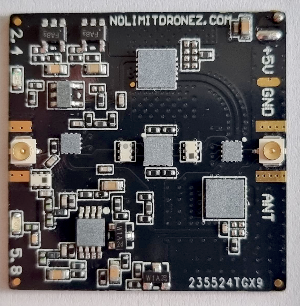
NLD 2.5W Bi-Di Signal Booster Kit for DJI drones
NLD sells you 2 boosters one for the AC one for the RC.
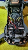
I have the AC side installed and working, it has 2 leds blue for 5.8ghz red for 2.4ghz, it switches automatically.
Power comes by piggybacking from the battery to a stepdown DC-DC regulator outputs 5.10v and then to the booster which connects to the right side antenna.
So it basically boosts only the right side antenna.
Testing with only the AC booster in FCC mode (not boost mode, nld warns against using boost mode as and i quote "will overgain the booster") installed yielded no appreciable range extension or signal strength. However i get RC signal lost and still have video feed from the drone, so there's that.
One month ago when i received the boosters, the second one was dead, NLD sent me a replacement one, and right now i am having a lot of trouble installing it in the remote.
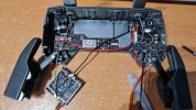
Its very fiddly, as there is not enough space in the remote, everything is very tightly packed.
After some hours of careful inspection i managed to make all the connections inside the RC.
Basically power comes straight from the battery (4.2 volts), and then to a switch (to switch the booster on and off, otherwise the booster will be always on) then again to a DC-DC (5.10v) regulator and then to the booster.
You have to drill the remote back side to expose the switch.
On the example video they have on their page, the guy connects the booster to the RIGHT antenna essentialy swaping the the two antennas, i presume because the antenna leads are not long enough to reach the booster.
So from the RC board left -> right antenna
Board right -> booster -> left antenna.
Again this boosts only one of the antennas.
The question for me right now is what each antenna on the RC does?
Which one is TX/RX, both of them? only the right one is TX/RX? Which one provides the downlink and which one the uplink?
Connecting the booster to the right socket or the left, shows different behavior from the booster judging from the led's. So the behavior of the two antennas are different.
Here's the problem though, connecting the booster either to the left or right socket and switching it on results on signal degradation judging from the image transmission state on the go 4 app, basically the entire signal line jumps up about 10 dbm to the "poor" state as described in the app. This is with the drone a couple of feet away, not flying.
So something is amiss, haven't done any flying yet, as the controller is in pieces as of writing because of testing, but clearly its not how it should be.
If anyone has any advice on the matter it would be greatly appreciated.
@AZDave you seem to know your stuff, any input on the matter?
Thanks
Attached picture of the booster inside the drone and the RC
NLD 2.5W Bi-Di Signal Booster Kit for DJI drones
NLD sells you 2 boosters one for the AC one for the RC.
I have the AC side installed and working, it has 2 leds blue for 5.8ghz red for 2.4ghz, it switches automatically.
Power comes by piggybacking from the battery to a stepdown DC-DC regulator outputs 5.10v and then to the booster which connects to the right side antenna.
So it basically boosts only the right side antenna.
Testing with only the AC booster in FCC mode (not boost mode, nld warns against using boost mode as and i quote "will overgain the booster") installed yielded no appreciable range extension or signal strength. However i get RC signal lost and still have video feed from the drone, so there's that.
One month ago when i received the boosters, the second one was dead, NLD sent me a replacement one, and right now i am having a lot of trouble installing it in the remote.
Its very fiddly, as there is not enough space in the remote, everything is very tightly packed.
After some hours of careful inspection i managed to make all the connections inside the RC.
Basically power comes straight from the battery (4.2 volts), and then to a switch (to switch the booster on and off, otherwise the booster will be always on) then again to a DC-DC (5.10v) regulator and then to the booster.
You have to drill the remote back side to expose the switch.
On the example video they have on their page, the guy connects the booster to the RIGHT antenna essentialy swaping the the two antennas, i presume because the antenna leads are not long enough to reach the booster.
So from the RC board left -> right antenna
Board right -> booster -> left antenna.
Again this boosts only one of the antennas.
The question for me right now is what each antenna on the RC does?
Which one is TX/RX, both of them? only the right one is TX/RX? Which one provides the downlink and which one the uplink?
Connecting the booster to the right socket or the left, shows different behavior from the booster judging from the led's. So the behavior of the two antennas are different.
Here's the problem though, connecting the booster either to the left or right socket and switching it on results on signal degradation judging from the image transmission state on the go 4 app, basically the entire signal line jumps up about 10 dbm to the "poor" state as described in the app. This is with the drone a couple of feet away, not flying.
So something is amiss, haven't done any flying yet, as the controller is in pieces as of writing because of testing, but clearly its not how it should be.
If anyone has any advice on the matter it would be greatly appreciated.
@AZDave you seem to know your stuff, any input on the matter?
Thanks
Attached picture of the booster inside the drone and the RC
Attachments
Last edited:


.png")