

Cybernate, I have no doubt you witnessed that, but I would like to see the setup and check the calibration of the testing equipment. DJI publishes on the mavic datasheet 26 EIRP.
EIRP = Radiated power output from antenna ( Transmitter (dBm) - Cable_Loss (dB) - Connector_Loss (dB) + Antenna_Gain (dBi) )
Making a safe assumption that the controller has 0.5 db loss in cable/connectors and 3.8 dBi antenna gain, that would equate to the radio transmitter at 22.7 dBm, or 186 mW.
45mW is only around 1/4 of the FCC allowed EIRP for this type of setup. It is possible that DJI may dynamically adjust transmit power when the aircraft moves away from the remote. I know other technologies do this, but I am purely speculating trying to understand this low measured power output.
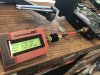
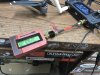
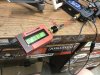
I didn't do the testing. The guy that did simply hooked up his meter to left side of controller and turned on controller and Mavic. It read 45mW in FCC mode and 9mW for CE mode. There is also a "special" version of DJI Go 4 that boosts the output to over 150mW, but I've heard it's not stable, resulting in overheated controller and potential disconnects and damage to controller.
You may be right, that the output is dynamic. I've also wondered about that.